
Technical Stuff
TORQUE AND REPHASE THEORY
XS650 CAMS
WHICH OIL TO USE
YAMAHA XS650 HI PERFORMANCE GEARBOX MODIFICATIONS
880cc ENGINE BUILD
CYLINDER BORES AND PISTON RINGS
MODIFYING THE ADVANCE AND RETARD MECHANISM
Inertial Torque and Rephased theory
A conventional two cylinder 360 degree engine (XS650) has its crankpins all in the same plane, both pistons reaching TDC (top dead centre) and BDC simultaneously, occasionally called a flat-plane crank. It is this particular configuration which generates a force called inertial torque. This is independent of the main torque output generated by the combustion process and happens entirely because of the crankshaft layout.To understand it, first imagine a crankshaft on its own, no pistons or con-rods, spinning in friction-free bearings. There's nothing to slow it down or speed it up so it just keeps spinning at a smooth, constant speed. Now attach the con-rods and pistons, for the sake of this experiment, we'll make them frictionless too. As you spin the crank the pistons move up and down, and the whole system keeps on rotating and reciprocating. At this stage there's no combustion or valve gear or anything to confuse the issue, and crucially, there is no energy being put into our system and none being extracted or lost. This matters because it is a fundamental law of Physics that energy cannot be created or destroyed, only converted into another form - Mechanical Engineers refer to this as the first law of thermodynamics.
Within this system, the pistons are travelling at highest speed when they're approximately half way down their cylinders; at this point they have a lot of kinetic energy. Yet 90 degrees of crankshaft rotation later, both pistons are stationary, either at the top, or at the bottom. Their kinetic energy hasn't simply vanished because it can't: instead it's been transferred to the crankshaft, which was responsible for slowing the pistons down. As a result, the crank itself has increased its speed. Another 90 degrees on and the pistons are back up to maximum speed, accelerated by the crank which has returned some energy to them and in turn, it's slowed down again.
In a full rotation the crank will have sped up and slowed down twice, generating rapid negative and positive torque pulses completely independent of the torque produced by the combustion process. This constant pulsing torque is like a background noise to the main torque output. Although this torque production is not a result of burning fuel/air the scale of it is massive, dwarfing the conventional, output torque by up to a factor of four.
In a conventionally laid out XS650 engine at 7500rpm for example, the inertial torque swings from around 250 to –250lb.ft twice in every revolution of the crank.
Eliminating this inertial torque means you no longer have to make such great allowances for it in the driveline. Many clutches for example include metal springs or rubber bushes as a cush-drive in the back plate to soak up the inertial torque pulsing so it doesn’t damage the gearbox. With this gone the cush-drive can be deleted and the connection between crankshaft and rear wheel is more direct, improving feel for the rider.
90 degree V-twins are famous for their drive out of corners, and sure enough, they have almost zero inertial torque. As one piston is accelerating so the other is slowing down, and when one is stopped the other is at maximum speed. This is an important factor in why Ducati’s have been able magically to accelerate out of corners faster than more powerful conventional fours.
On a Yamaha XS650 that has been rephased, these fluctuations are all but eliminated. In this layout one crankpin is located at 83 degrees advanced to the other. So as one piston is slowing down and losing energy to the crank, another is almost exactly at the point of maximum acceleration (actually 75 degrees ATDC) taking the same amount back. At no point do both the pistons stop together, as they do on a traditional XS650 crank. Instead the energy flow is evened out and the rotation of the crank is almost completely smooth and steady.
The Maths…..
I’ve used a XS650 standard bore engine ( 75mm ) as an example, revving to 7500 rpm, and to make the calculations much easier, I’ve assumed the piston movement is symmetrical so it’s at maximum speed half way down the bore. In fact this is only true with infinitely long con-rods but real ones make the mathematics too complex, and the result isn’t very different anyway.
A piston mass of 0.4kg (I’m going metric for this as it makes life much easier...) although as the con-rod and gudgeon pin move with the piston their weight should be included too, so 0.4kg is rather low and the real inertial torque figure will be much higher.
The aim is to calculate the acceleration of the piston as it moves from stationary at TDC (top dead centre) to its maximum speed, and from that we can calculate the force exerted on it by the crankshaft through the con-rod. Knowing this force and the distance of the crankpin from the crankshaft’s centre (half of the engine’s stroke) allows us to calculate the torque.
* Step 1 – Find the piston’s maximum speed (V)
In our XS650 engine this occurs approximately halfway down the bore where piston speed is the same as the crankpin speed. At 7500 rpm the crank rotates 125 times per second. The diameter of the circle the crankpin (big end) travels is π x the stroke, 74 mm on the XS650. That’s a peak speed (v) of π x 0.074 x 125 = 9.25m/s (metres per second) That’s 0-34mph in 37mm
* Step 2 – Find how much time (t) the piston takes to travel from TDC to max speed:
At 125 revs per second, one rev takes 1/125 seconds = 0.008 seconds. Max speed is reached in 1/4 turn of the crank, so t = 0.008/4 = 0.002 seconds.
* Step 3 – Calculate the piston’s acceleration (a), using a = v/t
a = 9.25/0.002
= 4625 m/s-2 (That’s huge. Earth’s gravity, 1g, is 9.81 m/s-2 so a XS650 piston experiences up to 470 G... this is why they need to be strong
* Step 4 – Calculate the force of the con-rod pulling and pushing on the piston to accelerate it, using force = mass of the piston (m) x acceleration, F = ma:
F = 0.4 x 4625 = 1850N (N is Newton’s, and 9.81 Newton’s is the same as 1kg, so a piston experiences more than one and three quarter tons force as it accelerates at this rpm).
* Step 5 – The torque (T) generated by this force on the crankshaft, using torque = force x distance from rotation centre (half the stroke, 0.0370m)
T = 4625 x 0.037 = 171Nm.
So we British can understand, that’s a massive 123lb.ft of torque more than the engine makes in the usual way! And this is only from one piston, and there are two doing it...
In other words, spinning at 7500rpm, the inertial torque in a XS650 engine due to the pistons peaks at 246 lb.ft.
And you wonder why it vibrated …..!
BACK TO TOP
XS650 CAMS
The XS650 has relatively recently gone through quite a rebirth, although its popularity in the late 80s and 90s waned, with the interest in vintage Japanese bikes at an all time high, it is only right and proper that the best Japanese twin made should be at the height of this interest.
There are a whole host of improvements available for these bikes and there are many manufacturers worldwide who will provide parts and services to keep these twins alive. I supply a few of them, rephasing is one of the best known current modifications. There is an upgrade for almost every part for the bike that is “evolution”. These bikes, like every commercial enterprise, were built to a price and some of the design reflects this. However, now many have the luxury of an attentive owner who is quite willing to improve the original design by spending money on quality upgrades.
One of the improvements possible, although not one often addressed , is cam shaft replacement. The XS650 camshaft was never a performance item; its design brief would have called for good fuel economy, ease and cheapness of production and reasonable power for an engine of its type. Recently I set up a dial gauge and measured the valve lift, measured against crank rotation. I have done this dozens of times to check what the valve is actually getting lifting, compared to what the cam vendor or manufacturer states.
What I found was quite a revelation to me. I was fully aware that cam design along with everything else has taken huge leaps forward since 1968/9 when these engines were on the drawing board. The cams in an XS650 both early and late styles lift the valve of the seat very slowly.
These are the figures for the inlet valve lift measured at degrees before top dead centre (BTDC)
|
Inlet
valve lift |
Degrees
BTDC |
|
0.002 |
93
BTDC |
|
0.004 |
71
BTDC |
|
0.006 |
49
BTDC |
|
0.040 |
11 BTDC |
|
0.050 |
7
BTDC |
Similarly the inlet valve closing after top dead
centre ATDC
|
Inlet
valve lift |
Degrees
ATDC |
|
0.050 |
43 |
|
0.040 |
47 |
|
0.006 |
77 |
|
0.004 |
95 |
|
0.002 |
122 |
If the
inlet valve tappet clearance is set at
0.002 the
overall inlet cam timing event is 93+180+122 = 395 degrees, if the
tappet
clearance is opened up to just 0.006 then the inlet cam event total is
49+180+77 = 306 degrees.
The late XS650 stock cam holds the valve off its
seat for nearly 45 degrees before it actually lifts more than 0.005;
this is just
wasting power, and compression.
Setting
the intake valve clearance at .006" versus
.002"
means you have lost 89 degrees of the valve opening event. (44 degrees
on the
intake opening side and 45 degrees on the intake closing side) It
won’t lose
you any flow or power however, as the valve was only a couple of
thousandths of
its seat.
The
intake valve is just loitering off the valve
seat but is
still open when it could have opened 44 degrees later, and closed 45
degrees earlier,
allowing for greater dynamic compression, and more time for the valve
to lose
its heat through the valve seat. There is no flow advantage with the
slow
opening and closing rates that leaves the valves open for 89 degrees a
few
thousandths off the seat except burned valves, lost mixture and
compression.
The
early Yamaha XS650 ( XS1, XS2 etc) had tappet
clearances
of 006" and .012" for the intake and exhaust respectively.
It’s
one
of the reasons the earlier engines perform better, they do have a
slightly
wilder camshaft (not much) but most of the increase in compression
comes from
just keeping the valves shut longer .
Setting
valve clearances to the LATE stock cam
specs just
contributes to reversion and lost compression with these antique slow
cam lobe
opening and closing rates.
The
design of the cam echoes the “cooking
model” cams of the
British bike industry, but as Yamaha engineers had no previous four
stroke
experience what else could they copy err…. benchmark.
I have
checked stock and performance cams from the
opening
to the closing in thousandths per degree every 10° of crank
rotation, just to
check cam profiles. Most of the newer design (non
symmetrical) cams
open the valves faster than they close them, but both rates are very
much
faster than the old style cam designs of the past. Computer modelling
cam
profiles helps in this area.
The
late XS650 cams set at .002" intake tappet
setting
is ridiculous. I
can’t think of
another
OHC engine with valves this size that has such small clearances, the
camshaft
has a run-out of over 0.002 in many cases and setting the tappets to
this small
clearance will allow the valve to stay open perpetually. It is an
effort by
Yamaha to reduce engine noise, but this is not the way to do it.
I
set all the tappet clearance at the early
settings of 0.006 and 0.012. It allows in more oil, and allows for a
generous
growth in the metal parts, remember….. A loose tappet is a
happy
tappet.
WHICH OIL TO USE?
A lot
of people ask me what oil to run in their
XS650, it is one of those emotive subjects where everyone has their own
ideas. I did some research a few years back and decided to run mine on
Mobil 10W 60. It is a high end synthetic, designed specifically for use
in older engines to prolong their life; it sounded just the ticket for
an aging XS650.
It is common to find XS650 owners who won't use synthetic
engine
oil, claiming it is too slippery and the clutch will pack up. Similarly
they say that the modern oils don't cater for engines with
combined gearboxes, and to a large extent modern oils do not address
this phenomenon. This is due to a lack of an additive called ZDDP; one
of the main additives that ensures that the gearbox is
“protected” is ZDDP.
A lot
of people will already know that ZDDP is
Zinc Dialkyl Dithio Phosphatese, and most importantly it provides
excellent anti wear protection. ZDDP used to be in lots of quality
engine oils. When it greatly increases in temperature it fragments and
coats the metal surfaces with Zinc, particularly useful on gears,
camshafts, flat top cam followers etc. The Phosphate part then acts as
a dispersant making any carbon produced dissolve in the oil and not
stick to the inside of the engine.
However, it was found that it caused problems with Diesel Particulate
filters, so it has been dropped from a number of oils. It is also said
to be less than friendly to catalytic converters, but it seems this is
only the new generation of cats. Bear this last piece of information in
mind, when selecting diesel oil as suggested by many US based XS650
based forums and businesses.
Mobil-1 Extended Life 10w60 does indeed include ZDDP. Not only this,
but it has 1300 Parts per Million (PPM) which is comparable to the
obsolete but superb Mobil 1 Motorsport 15w50.
The "10w60 extended life Mobil-1" product is fully synthetic, made from
virgin base products.
I have been running it in my XS1 for years, and all the rest of my
fleet. I experience no clutch slip on any of the bikes. Just thought I
would share my findings with you out there. Hope it helps.
Yamaha XS650 Hi Performance gearbox
modifications
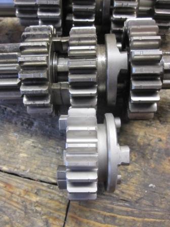
The Yamaha XS650 gearbox is a robust design, a vast improvement in
terms of the selection and quality of manufacture compared to its
contemporaries. It was improved somewhat when Yamaha changed the gear
tooth shape in 1978 to a more rolling design. By increasing the area of
the gear tooth in engagement at any one time, it decreased individual
tooth loadings. To differentiate the old and new tooth shapes, Yamaha
machined a shallow groove around the periphery of the gear.
However the gearbox is not flawless, and if you ride really hard or use
the bike for competition purposes, then the gearbox can experience
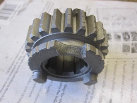
mechanical flaws. Pictured below is a gear taken from a gearbox on a
road bike, one of the driving “dogs” has broken off
the gear. This is almost always caused by decelerative forces, not the
driving power or torque, in effect reverse torque production, the end
result when the gearbox is subjected to the immense forces produced
when substantial engine braking is used.
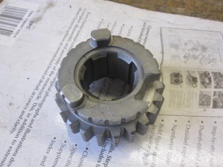
This is the 3rd gear main-shaft on a late XS650 gearbox; as can be seen
the driving dogs are not overly wide, when the bike is ridden hard and
subjected to hard downshifts, the inertia of the bike is transmitted
through the gearbox, and ultimately in this case through three drive
dogs. The forces are high enough to shear the driving dog from the main
body of the gear.
However as we all know Yamaha are past masters of designing and using
the same parts for many different vehicles in their line up,
it’s called parts commonisation, and is one of the secrets to
minimising your production costs and maximising your profits.
Often you see for instance a clutch lever appear on bikes from
different years, when you check it out you find they have using it for
25 years, clever stuff. This methodology extends (thankfully) to the
engine designs as well. One of the ways this can help XS650 owners is
in the gearbox, the much stronger gearbox parts from Yamaha XS750/850
(the triple made from 1976 to 1981) can be used in the XS650 gearbox
from 1978 to 1984.
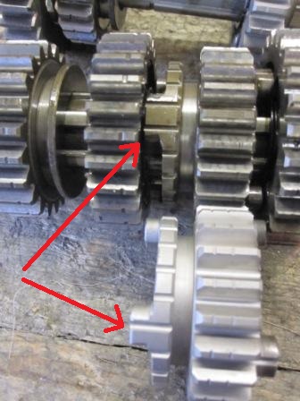
The main parts that mostly suffer in the XS650 gearboxes are the
sliding gears. These gears are the ones that engage with the
freewheeling gears to transfer motion to the rear wheel. The Yamaha
XS750 gears can be used to provide a much stronger alternative to the
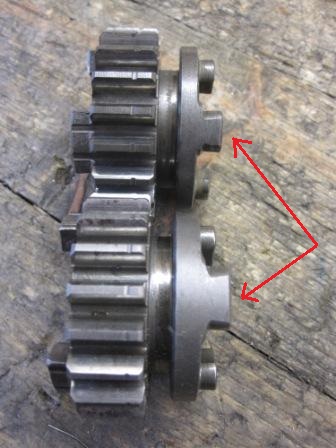
original items. In the photo above, the width of the engagement dogs
(arrowed) can clearly be seen to be wider and therefore stronger. This
is the 3rd gear main-shaft which is the one that suffers the most from
abuse and high torque, the XS750 gear ( 1J7-17251-03-00 ) pictured has
a massive 35% wider driving dog.
The countershaft sliding gear can similarly be replaced with an XS750
item and is pictured below; in this case the XS750 3rd gear
countershaft (1J7-17131-01-00) has a 25% wider driving dog
The gears listed above have accompanying matched size gears which allow
use of the wider drive dogs. These must also be used, this is very
important; failure to ensure that the matching wider dogs and wider
slot gears are used as pair will result in at the very least terrible
gear engagement.
The parts numbers for the matching gears being
1J7-17231-03-00 3rd gear pinion
and
1J7 17151-04-00 5th gear pinion
The gears that are being replaced have the same number of teeth so the
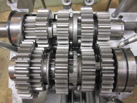
internal gear box ratios will remain the same. Pictured below is the
whole new assembly complete with the XS750 gears prior to having the c
clips and shims installed.
I sourced a good used 1978 XS750 gearbox from Fleabay for
£35, stripped out the relevant gears and built the whole
assembly back together, checking gear engagement and end floats on each
gear. I de-burred the individual gear pinions, and then shot-peened the
whole lot for increased fatigue resistance. This is the best you can do
to “Bullet- proof” the transmission. Check also the
Kickstart gear engagement, as it usually only engages ½ way.
This can be rectified by turning the back of the shaft away, and
milling 1 mm from the crank cases. It does require a spacer be made
also. If you need to do this mod or the gearbox work please email me
for more detail, as it is quite involved, and surprisingly not shown in
the Haynes manual!
Anatomy of an 880 cc engine build
I build quite a lot of
Yamaha XS650 engines, all the way from completely stock to full race
and everything in between. The XS650 is an excellent design and very
resilient to complete disregard of maintenance and outright abuse, and
is well enough made to allow significant power and torque increases
before major parts start breaking.
I was approached in 2015 by Mike Guilford and his son Martin to
assemble an engine for a sidecar Moto-cross team. Since then we as a
team have had a fair deal of success, culminating last year (2016) in
Martin winning the Twin-shock chairs championship on an 840cc engined
XS650.
They say that “racing improves the breed” and it
could not be truer. In the last two years we have learnt a lot about
big bore XS650 engines, and how to keep them in one piece.
With this in mind I decided to do a step by step build on an XS880
engine. These engines can be reliable when built properly, and
strangely enough it's not that much hard work to get right,
attention to detail and cleanliness are the objectives of
paramount
importance.
To build a rephased 880cc engine the following specialist parts are
required. The rest of the engine internals can be checked for wear and
tear, and if it's all OK can be re-used. The gearbox does get
a tough time with big bore engines, but if you don't ride a
motocross rider, they should be OK. (See gearbox
modifications article to
see what can be done)
Heiden bare big fin cylinder
87mm bore ductile iron cylinder liners. (Ductile iron grade 700-2 is
twice as strong as cast iron)
87.5 mm copper big bore head gasket
Bored crank cases
Rephased 533 crank
277 rephased cam shaft
Step one is to acquire a good set of crankcases, whether it be
the set
on your existing engine or a set from your spares stock. (All
crankcases from 72-84 are essentially identical, only XS1/B cases are
different). For this build I purposely chose the roughest set in my
spares stock to illustrate what can be done with a little hard
work. Inspect them carefully for damage, the kick-start lug
breaks, damaged threads, and very rarely cracks near the
studs.
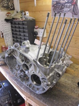
Cases before any work
Clean them till they are spotless, and then clean them again! Remove
all the old gasket sealer that Yamaha used, it will have turned brown
with age. Remove the starter boss, this can be done by removing the
screw and then putting the crank case on the gas hob, in around ten
minutes it just falls out.
I rarely run starter motors, they weren't very good when they
were new, and even the best ones won't get far with an 880cc
engine. I turn the defunct starter motor into an additional sump for
increased cooling.
Remove the cylinder studs, do this with heat and two nuts tightened
against each other, do NOT undo them with a pair of plumbers Stillsons
or vice grips, these studs will keep your head bolted down, and any
damage may cause them to fail.
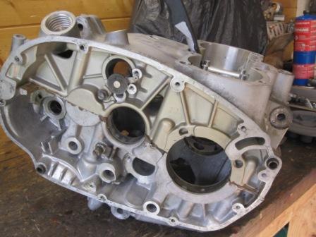
Cases cleaned and studs removed
The crankcases will need the crankcase mouths increased to 91.00 mm, to
accept the larger ductile iron cylinder liners. This
operation is done on the CNC mill at my friends workshop. We set the
Heiden big fin cylinder up on the crank-cases, measure very accurately
the cylinder bore centres, then remove the cylinder and bore the cases.
Doing it this way ensures that the liners will be exactly central in
the new crank-case holes, something that they are often not from the
factory.
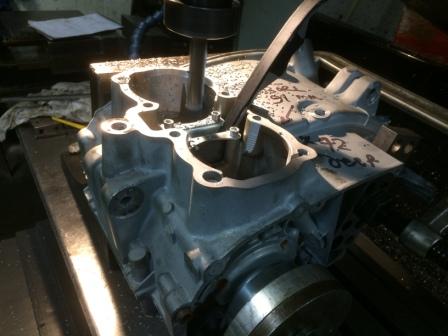
Cases being bored
As a precaution against the cases cracking, I send them away to be
shot-peened. This process utilises steel shot projected at a measured
velocity against the work piece. The shot compacts the surface, and
decreases the possibility of cracks forming, which always start at the
surface of a material.
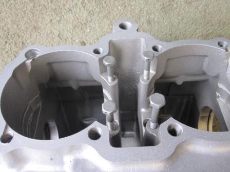
Shot peened cases
The weak point with the cylinders when an 840 or 880cc bore is
considered, is the proximity of the dowels holes to the cylinder bore,
these big bore engines can very occasionally blow a head gasket. To
prevent this I machine up inserts which are welded into the dowel holes
and then re-drilled at 10.5mm to give as much gasket surface as
possible. This has proved to be beneficial in our race engine; we have
not blown a head gasket in a whole race season.

Dowel hole welded in cylinder
The next operation is to swing the bare Heiden cylinder in the lathe on
a specially made Smedspeed tool, and then bore the cylinder out to
accept the larger liners. The alloy cylinder is initially bored
0.010’’ undersize, the cylinder is then precision
honed to give a high surface finish, and a 0.005’’
interference fit. These steps ensure the best heat transfer possible
between the ductile iron liner and the aluminium cylinder. After boring
to a piston clearance of 0.003’’--
0.0035’’ to suit the Wiseco pistons, the cylinder
top is surface ground to ensure complete flatness.
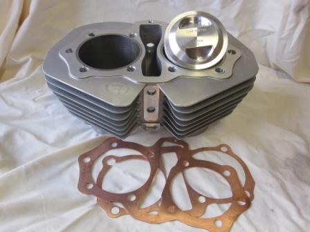
Wiseco piston and cylinder
The finished work on the cylinder can be seen below. The original dowel
holes are blocked, welded, and then re drilled. The dowel holes are
moved to the outer two 8mm bolt locations. The dowels are readily
available Yamaha outer case dowels, Part number 91810-08016 (9.8-12-16
mm)
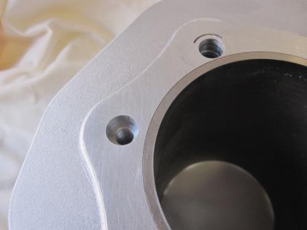
On the basis that if a little is good, then a lot must be much better,
I
decided to do the same thing to the head, not just the dowels holes but
all eight bolt holes. It's not a big deal to do
actually. I set the head up on the mill, centred a 13.5 mm drill on
each head-bolt hole, and then drilled to a depth of 7 mm, followed by a
14mm reamer to a depth of 8mm, then pressed in a slightly oversize 14mm
plug. The 12mm diameter dowel location in the head can be seen on the
bolts that are located under the spark plugs; the depth of cut is 5mm
from the head surface.
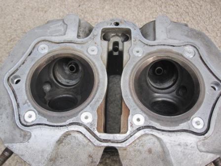
Head bolt holes plugged
After the plugs are welded, the head is skimmed, then the cylinder is
bolted to the head, and a 10.5mm drill centred in the the cylinder bolt
holes
to drill the plugs.
The crankcase to cylinder dowels need ‘reducing’
for the cylinders I supply, the liner within the cylinder is 3 mm
thick, whilst outside, the spigot, is only 1.75 mm thick, the
picture
shows what must be done to the dowels to stop then cracking the
liner.
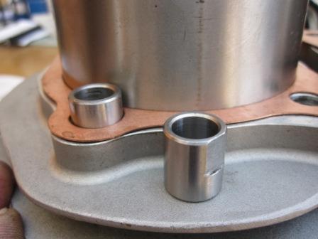
Modified 880 cylinder dowel
Squish clearance

Ceramic coated Wiseco piston crown
The reduced piston to head clearance will actually lift the
compression
a little further, however the beneficial squish effect will add
considerable turbulence created by the tight clearance and this will
actually reduce detonation and increase the burn of the fuel air
mixture. The ignition timing can then be reduced from the stock 38
degrees to around 33-34 degrees (the actual figure will be found by
dyno tuning).
The 880cc engine must use as a bare minimum NGK BP8ES spark plugs or
the fine wire equivalents.
The 880 kit can only be used with a 533 crank. This crank was used on
European only XS650 engines, it has a larger 29mm crankpin, and the
connecting rods have 140mm centre. This gives a rod to stroke ratio of
1.89:1 which reduces piston side thrust loads, and subsequent wear
rates. Ensure you have a 533 crank; the 447 and 256 cranks will not
work with the 880 conversion. If your crank is in excellent condition
it can be re-used, but if it is in any way suspect then replacement of
the worn parts is recommended for long engine life, these engines are
very high torque and will “spit out” any suspect
parts.

Knackered crank
The crank above was in a shocking state when I had it given to me. I
purposely picked a crank that to all intents and purposes looked
trashed, and to illustrate what can be done. I disassembled it, masked
off the bearing areas and then blasted it with chilled iron to get the
rust off. Amazing what throwing some blasting media at a rusted crank
can do!
It has new main bearings (4) and new connecting rods; it has also been
dynamically balanced to 53% balance factor to suit the Wiseco pistons.
Rephased engines are very smooth compared to stock engines, and the
heavier in mass the replacement piston, the nearer it is to the correct
balance factor it gets without balancing work.

Rebuilt 880cc 277 degree rephased crank
Dynamically balancing the XS650 crank is a long winded and expensive
option. The crank has
to be built without the con-rods, trued and then taken along with all
the reciprocating items to the specialist balancing firm. They balance
the crank weighing all the parts and correcting any
imbalance to the chosen factor. The crank has then to be disassembled,
and rebuilt this time with the connecting rods, then trued and
then TIG welded.
It's a lot of work, but I wanted to see how smooth one was
compared to the unbalanced option.
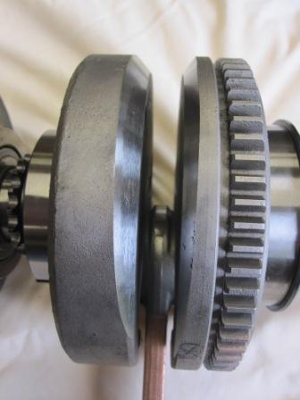
Dynamic balancing work on crank
The gearbox can have a hard time on a big bore or bored and stroked XS
engine, the sidecar boys regularly get the engines to spit out the 3rd
gear mainshaft. I took this one out of a pile of spares I bought, it
might have been raced, who knows.
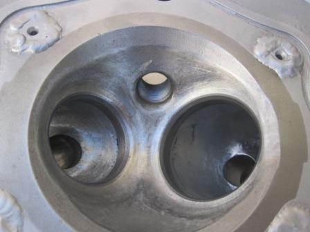
The Wiseco pistons provide for a compression ratio of 10.5:1. This is
really on the upper limit for good fuel without detonation occurring,
if detonation occurs it will ruin even the best built engine. As a
precaution, and to make it a little easier to start and to get some low
valve lift air-flow, I remove all the rough edges from the combustion
chamber, Yamaha specified this in one of there many racing tips sheets.
It drops the compression a little which will only help. I kept the
ports essentially the same shape as stock, as I want to keep a
lot
of velocity in the ports, I just smoothed out the rough bits.
I
have written a whole lengthy article on gearbox
revisions, it might
be worth doing if you ride really hard, otherwise I wouldn't
bother unless you just want to.
The assembly is fairly simple, I use a mild cam, it's a copy
of a Shell #1 with a bit of minor tweaking to make it less tappety.
These larger displacement engines tend to like less rpm,( max rpm
7000) it will keep them together longer,
and make them more fun too ride. I have seen a fair few dyno sheets
from these engines, and 65-68 RWHP is easily attainable. Thats not much
of double the stock output !
The 880cc conversion for the XS650 has been about for many years, we
did a few when I was in my twenties and that was quite a while ago. The
procedure then was to use Yamaha XT500 pistons and bore the existing
cylinders, and fit some sort of adapted car cylinder liner.
It's OK I suppose.... just about, but it's not
really right. What I have tried to show here is how with modern parts
and processes this conversion can be improved a little. This is not an
exhaustive guide to building one these engines by any means,
it's just a heads up for things to look out for or consider.
I couldn't find any information when I considered doing this,
so I thought quick, get it down on paper, it might just help someone.
BACK TO
TOP
CYLINDER BORES AND PISTON RINGS
CYLINDER BORE FINISH AND PISTON RINGS
What’s the best type of cylinder bore finish for an XS650?
Have you ever thought about it? If you are into that kind of thing most
would say it’s a finish that allows the rings to seat quickly
and completely so the engine doesn’t use oil and to provide
the best sealing against compression gas escape.
As far as XS650 are concerned that can be accomplished using a process
called plateau finish. The surface finish must also meet the piston
ring manufacturer’s specifications and have the proper
crosshatch so the cylinder walls will retain oil and provide adequate
lubrication for the rings.
BORE FINISH
Regardless of what kind of rings or liners are used in a performance
engine, piston rings will seat best and last the longest when the
cylinder bores are given a plateau finish. A plateau finish essentially
duplicates a “broken-in” bore finish; it is so
called as the finish at a microscopic level emulates a series of tiny
plateaus. This process minimizes the scrubbing and wear on the rings
when the engine is first run and in the subsequent running in process.
When this process is done correctly it will provide a flat, smooth
bearing surface to support the rings whilst also retaining oil in the
crosshatch valleys to properly lubricate the rings.
Most ring manufacturers recommend using a two- or three-step honing
procedure to achieve a plateau finish. First, rough hone to within
.003″ of final bore size to leave enough metal for finish
honing. For performance street or racing engines hone with #220 grit
silicon carbide stones (or #280 to #400 diamond stones) to within
.0005″ of final size. Then finish the bores with a few
strokes using a plateau honing tool, cork stones or a flexible abrasive
brush.
For street performance engines an average surface finish of 15 to 20 Ra
is typically recommended. For racing, it is possible to go a little
smoother, but care must be exercised to ensure that the cylinders
don’t become glazed. These Ra numbers would be meaningless
without a surface profilometer that can measure them, which the boring
firm I use have of course!
CROSSHATCH
Cylinder crosshatch is also important because the amount, the depth and
angle of the crosshatch in the cylinder bores determines how much
lubrication the rings will receive and the rate of ring rotation. Ring
manufacturers typically recommend a crosshatch angle of 22° to
32° as measured from horizontal and uniform in both directions.
BORE GEOMETRY
Bore geometry is especially important in performance engines because of
the higher cylinder pressures they generate and the higher rpms at
which they operate. Torque plate honing is a must with all performance
engines to compensate for the bore distortion that occurs when the
heads are installed. Yamaha XS650 engines suffer a fair deal of bore
distortion, the cylinder is air cooled, and in operation will be hotter
at the rear than the front, this unequal heat distribution will cause
distortion. The distortion can be minimized by using a thick cylinder
liner in a well supported cylinder.
For any engine size over and including 750cc the very best cylinder is
the Heiden BIG FIN cylinder, it is very thick and will resist
distortion well. In addition to this the use of ductile iron cylinders
which have twice the strength of stock cast iron liners is a good idea.
Designing them to be of thicker section only helps in minimizing bore
distortion. The selection of the best materials and use of good
processes including torque plate honing/boring and plateau honing will
go a long way to keeping the bore perfectly straight and round for
superior ring seal and power. I use the BIG FIN cylinder a lot, and fit
my own design ductile iron liners, shrunk in to higher interference to
maximize heat transfer
Typically, cylinder bores tend to squash in and deform in areas that
are next to the cylinder/head studs. The higher the clamping load (head
torque) the more the studs will try to push in towards the bore
centre. Bore distortions can prevent the rings from
conforming to the surface, allowing more blowby and oil consumption. If
the cylinders are not straight, the rings can bounce away from the
surface and lose their seal, not what you want in a racing
engine.
PISTON RINGS
Performance pistons for Yamaha XS650 engines are using thinner and
lighter rings than ever before. Thinner, low-tension rings reduce
friction for more usable horsepower. Less weight reduces ring groove
pound out. Narrower rings also allow tighter tolerances and less
blowby. All highly desirable things when you’re building a
performance engine. But they also require rounder, straighter cylinder
bores than ever before.
One of the reasons for thinner rings on 533 pistons is they are short
in the compression height, (the distance from the gudgeon to the top of
the piston deck). Longer connecting rods with shorter pistons change
the combustion dynamics and provide better angularity during the power
stroke. Shorter 533 pistons also weigh less, which means the engine can
rev higher. But when the piston is shorter, the rings have to move up
higher. This means they have to be narrower, stronger and more heat
resistant because the top ring is closer to the combustion chamber.
All good pistons (Wiseco, Wossner, JE) use either ductile iron or steel
rings. Ductile iron has roughly twice the tensile strength of grey cast
iron, and three times the fatigue strength. Steel rings, by comparison,
have almost four times the tensile strength and fatigue strength of
grey cast iron.
So what does this mean inside an engine? It means ductile iron and
steel rings can survive in harsh environments that may be too demanding
for grey cast iron rings. Stronger rings reduce the risk of ring
breakage under severe loads. Steel rings also show less side wear and
ring groove wear.
RING END GAPS
The Old Skool philosophy of gapping piston rings said the end gaps on
second compression rings could be tighter because the number two ring
is not exposed to as much heat as the top ring. The current perspective
says it’s better to open up the second ring gap 20 to 30
percent so pressure doesn’t buildup between the rings and
cause the top ring to lose its seal at high rpm. The result is better
compression, better piston cooling and reduced oil consumption.
For XS650 engines running 80mm pistons (750 cc size) a top ring end gap
of .004″ per inch of bore diameter is often recommended for
stock or performance work.
That translates into a top ring end gap of between .012″ to
.013″. But this may vary depending on the power output of the
engine.
For oval or track racing, the recommended end gap is somewhat larger
(.0045″ per inch of bore diameter). With an 80mm bore, that
would be an end gap of .014″ to .015″.
Getting rid of the end gap altogether can also improve sealing, cooling
and horsepower. Gapless rings eliminate the gap between the ends of the
ring by overlapping slightly. Gapless rings are available in popular
sizes with various wear-resistant face and side coatings. Total Seal
make excellent rings for this application, but probably only for
racing; I ran them on a street Harley for years though.
CLEANLINESS
It’s my mantra, clean everything until it’s
spotless, and then go back and do it
again……….I need to say a few words
about cleanliness. All your efforts to produce an ideal bore finish
crosshatch and near perfect geometry will all be ruined if the
cylinders are not thoroughly cleaned after they’ve been bored
and honed.
Scrubbing with hot, soapy water is still one of the best ways to remove
the honing debris that will trash piston rings and piston in very short
time if not removed.
I fill the sink full of the hottest water I can stand (whilst wearing
rubber gloves) and scrub the bores with a nylon washing up brush until
I am bored, then quickly dry them to avoid rust. Once dry, wipe the
cylinder out with WD40 and if there is any grey showing on a white
cloth, go back and wash them again. If you do this you can be sure that
any damaging particles will have been removed from your bores.
I have outlined above the process I use for racing engines. Racing
improves the “breed”, all the practices we utilize
for racing also assist the street rider build a better engine, whether
it is for mild or high performance work.
MODIFYING THE ADVANCE & RETARD MECHANISM
IGNITION TIMING FOR MODIFIED ENGINES
An often neglected but important area when tuning an XS650 engine is the ignition system. Tuned and modified engines have different advance characteristics and requirements from a completely stock engine. Adapting the advance curve to meet these requirements using the standard mechanical advance mechanism is not that difficult a task, once the reasons behind why are understood.
Correctly setting the advance curve for a modified engine can make a considerable difference to the tractability of the engine as well as ensuring that the engine is giving its best power wise.
WHY AN ENGINE NEEDS MORE ADVANCE AS ITS SPEED INCREASES
When the compressed mixture inside a cylinder is ignited it takes time for the flame front to reach the piston and for the expanding gases to start pushing it down. The time that this takes changes according to a number of variables such as mixture strength, how well the cylinder has filled (dependent on volumetric efficiency and throttle opening), compression ratio and combustion chamber shape. Given the same circumstances of mixture strength, cylinder filling and CR, the time taken for the mixture to fully ignite and burn is the same regardless of engine speed. At increasingly higher RPM however, the time available for this burn to take place is correspondingly less, so it follows that you have to start burning the mixture earlier in order for it to push on the piston at the right time. This is the basis for increasing ignition advance. Too much advance and the burning mixture hits the piston as it rises (pinking or pinging), too little and the flame front reaches the piston far too late which causes sluggish performance and overheating.
HOW THIS IS ACHIEVED
The XS650 ignition system contains a centrifugal mechanism that advances the ignition timing automatically as engine RPM increases. There are a pair of weights which under the effects of centrifugal force get thrown outwards; this effect is greater as RPM increases. The weights are controlled by two small springs that restrain them progressively. As the weights move outwards they exert a turning force on the advance rod. This moves them in the opposite direction to the camshafts rotation, thereby causing the points/electronic trigger to actuate earlier and advancing the ignition timing. As engine speed increases the weights overcome more of the spring's tension and advance the timing still more. There is a stop that limits the amount of advance that the mechanism can provide.
WHY A MODIFIED ENGINE REQUIRES TIMING CHANGES
A standard engine has to run acceptably well over a wide range of operating conditions, but still has to deliver good economy and flexibility. Consequently the engine is tuned to give good low down performance and will use conservative ignition timing and fuel settings. It also has to cope with occasional poor quality fuel and changes in altitude changes (not in the UK) that can affect the engines behaviour.
A highly tuned engine generally is not designed to give good performance below 1800-2200 RPM and indeed below this level, the volumetric efficiency of the engine is affected. The more extreme the cam profile, the worse this situation becomes. This means that the effective cylinder filling (volumetric efficiency) at lower RPM could be poorer than with a standard engine. The cylinder filling is affected to such an extent that the effective compression ratio is lower than the static or calculated ratio. To offset this the tick-over or retarded ignition timing should be advanced. The less dense mixture requires more time to burn, hence the change.
The engine speed at which maximum advance is reached also needs to be later for a highly tuned engine, say 3500-3800 RPM. However due to the higher compression that tuned engines use, which increases the speed of the burning fuel air mixture, it needs to have less overall full advance, typically 3-4 less than the specified 38 BTDC of the stock engine.
ESTABLISHING STATIC ADVANCE REQUIREMENT
The static advance requirement for a modified engine is very much dependent on the duration of the cam fitted. As stated before, the longer the duration of the cam, the more it will affect low engine speed performance. To compensate for this loss, more advance is required to help the burn.
ESTABLISHING MAXIMUM ADVANCE REQUIREMENT
Notwithstanding the compression ratio and other factors, the main characteristic that determines the maximum advance setting is the shape of the combustion chamber and the position of the spark plug.
Below is a chart showing a typical and ideal advance requirement for a modified engine, the engine speed at which maximum advance should be reached is 3250-3500RPM, advance should start at around 1300RPM and be all-in by this figure.

MODIFYING THE MECHANISM TO LIMIT FULL ADVANCE
Standard XS650 advance mechanisms have the rate of advance controlled by two springs attached to the centrifugal weights. The two springs are of the same tension and length. To limit the full advance, the limit stops must be bent inwards (carefully), do not be tempted to do this with materials such as araldite or filler, it will simply drop off or wear out. The stock springs will have lost their tension over time, and as a result the ignition curve will be much faster, exactly what you don’t want on a tuned engine.
If the advance springs are too weak, then maximum advance will occur at considerably less than the 3500-3750 rpm ideal setting. If the springs are too strong then maximum advance will occur well beyond this setting. To be safe, the springs should prevent maximum advance being reached before 3500RPM.
If the advance ramp starts before 1300RPM, then this indicates that the initial tension on the springs is insufficient, so it will be necessary to bend the posts to increase initial spring tension. By bending posts to increase or decrease initial tension it should be possible to make the advance ramp very close to the ideal, which is a steady increase in advance between 1300RPM and 3500RPM. The highest acceptable rpm at which maximum advance should be reached is 4000RPM, the lowest is 3200rpm.
These figures are not hard and fast and will depend on many factors, however from work I have done the figures suggested work well on tuned engines. A dial back strobe can be used to “map” the advance curve, and a dyno used to check your modifications.
Most XS650 engines will pink a little if they are ridden at unreasonably low rpm and in a high gear, so if this only happens at 1500RPM in a high gear, this is an unusual combination and is unlikely to be encountered in normal riding. When the rate of advance is correctly set it should give the engine a rock solid idle, strong progression and mid range performance.
Well.. That's all there is to it.
If you have properly followed the procedures outlined in the previous text, then the advance curve for your modified engine should be very close to ideal and you should be able to feel the difference in your engines performance. If you are in doubt, exercise caution, better too little advance and slightly poor performance, than too much and a ruined engine.
BACK TO TOP